


What is Cavitation?
All liquids undergo a phase change from liquid to vapour if the temperature is raised to the boiling pt for the applied pressure. Water for example boils at 100oC at standard sea-level atmospheric pressure ( 101.325 kPa ). As the pressure is lowered, the boiling pt for any given liquid is also lowered. The atmospheric pressure on the top of Mt. Everest ( 33.7 kPa ) is only some 1/3 rd of the sea level atmospheric pressure and as a consequence water boils at 71 oC.
A liquid can thus undergo a phase change to vapour by either raising the temperature or by lowering the pressure. Cavitation is the process by which vapour is formed by the lowering of the pressure.
When a liquid flows through a varying section duct, the velocity increases through the sections with lower cross-sectional area. This increase of velocity results in a lowering of the local absolute static pressure, and if this pressure falls below the vapour pressure of the liquid - for the given temperature - local boiling will occur. Vapour bubbles are formed, and these will travel with the liquid until such a time that the local static pressure is greater than the vapour pressure. At this point, the vapour bubbles will begin to collapse. This can result in severe damage to mechanical components in the vicinity of these collapsing vapour bubbles.
One area where cavitation is a particular problem is in the field of boat propellers. The forward surface of the propeller tends to experience a static pressure which is lower than the ambient pressure. Under certain circumstances such as for boats running at high speed, the pressure can fall below the vapour pressure of water and lead to cavitation. The image above shows a boat propeller that has been damaged by cavitation. This damage is caused by the bubbles collapsing in a higher pressure region causing shock waves which damage the surface of the propeller.
Cavitation can also lead to the propeller efficiency dropping drastically. Charles Parsons, the inventor of the steam turbine in 1884, initially found that the boat he built - turbinia - to test his steam turbines only achieved a top speed of 19 knts. After fitting a torsion dynamometer on the propeller shaft, he discovered that the propeller was absorbing all the power yet not providing the expected thrust. A cavitation tunnel was constructed to test various designs of propellers. Parsons concluded that more blade area was required and hence turbinia had its number of propellers increased from 3 to 9. Sea trials with this configuration garnered a top speed of 34 knts for the same engine power.
The cavitation number represents how close the pressure in a liquid flow is to the vapour pressure and hence the potential for cavitation.
σ = (P - Pv) / 0.5ρv2
ρ is the density of the fluid
Pv is the vapour pressure of the fluid.
P is the local absolute pressure of the fluid.
v is the velocity of the fluid.
For a given flow scenario, as the magnitude of σ is reduced, cavitation will begin to occur at some value of σ known as the 'incipient cavitation number' - σi. The number and size of the vapour bubbles will increase as the value of σ drops further below σi.
If at some point on the flow stream the local pressure begins to rise, these bubbles may collapse. This can lead to shock waves plus if the bubble is located adjacent to a structural surface, the collapsing bubbles can cause re-entrant jets. Consequently, surface damage can occur quite rapidly, as shown by the image of a propeller above.
Cavitation Failure Analysis
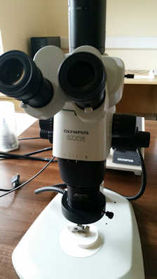
Flowcav offers its clients a Cavitation Failure Analysis service. Typically if a company has a component that they believe may have cavitation damage, we will examine the component under our Olympus SZX16 stereo microscope and take digital photo's.
We will then furnish the client with an inspection report that will show all the locations of corrosion and cavitation damage plus give an indication of the type of cavitation. Any suspect machining or manufacturing procedures that might induce the onset of corrosion and cavitation will also be highlighted.
It must be noted that it is not possible as a general rule to suggest design changes to a component purely based on analysis of a damaged component under the microscope.
This is because components are nearly always part of a system of components, and thus the flow regime is extremely complex and hence analysis tools such as CFD and 1D analysis are required.
Here at Flowcav we provide a service called Cavitation Minimisation that uses these tools.
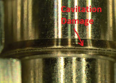
Shown below is a section through a unit pump from a large capacity marine diesel engine showing cavitation damage.
Cavitation Minimisation
Flowcav can design a component or system of components such that cavitation is negligible. Typically a company might already have a system design with known issues of cavitation. We can take their CAD files and do 1D and CFD analysis for the complete system.
First we carry out analysis to recreate the problem. Once this has been achieved we write a report on the findings from the analysis study.
At this stage the company might do a component/system redesign or Flowcav can suggest a redesign solution based on further system analysis.
Shown below is the CFD output for a "Cavitation Minimisation" study for a diesel pump from a multi cylinder, turbo charged engine. It is evident that this early prototype has quite severe cavitation issues.
Flowcav has 25 years experience in the field of cavitation and that combined with using state of the art analysis tools has led to our very successful track record.
Contact Flowcav now and we will be happy to answer any further questions you may have.